Friday, 26 February 2016

RAID

Standard RAID levels

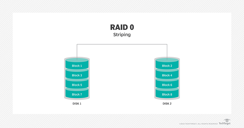
RAID 0: This configuration has striping but no redundancy of data. It offers the best performance but no fault-tolerance.


(1)RAID (redundant array of independent disks; originally redundant array of inexpensive disks) provides a way of storing the same data in different places (thus, redundantly) on multiple hard disks (though not all RAID levels provide redundancy). By placing data on multiple disks, input/output (I/O) operations can overlap in a balanced way, improving performance.


(2)RAID arrays appear to the operating system (OS) as a single logical hard disk. 


Standard RAID levels

RAID 0: This configuration has striping but no redundancy of data. It offers the best performance but no fault-tolerance.


RAID 0 diagram

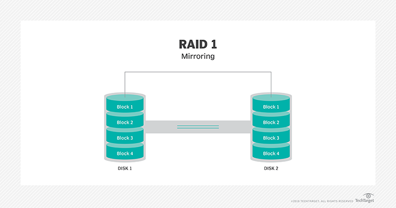
RAID 1: Also known as disk mirroring, this configuration consists of at least two drives that duplicate the storage of data. There is no striping. Read performance is improved since either disk can be read at the same time. Write performance is the same as for single disk storage.
RAID 1 diagram
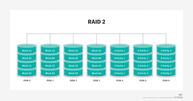
RAID 2: This configuration uses striping across disks with some disks storing error checking and correcting (ECC) information. It has no advantage over RAID 3 and is no longer used.
RAID 2 diagram
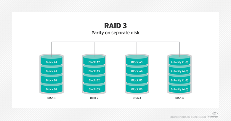
RAID 3: This technique uses striping and dedicates one drive to storing parityinformation. The embedded ECC information is used to detect errors. Data recovery is accomplished by calculating the exclusive OR (XOR) of the information recorded on the other drives. Since an I/O operation addresses all drives at the same time, RAID 3 cannot overlap I/O. For this reason, RAID 3 is best for single-user systems with long record applications.
RAID 3 diagram
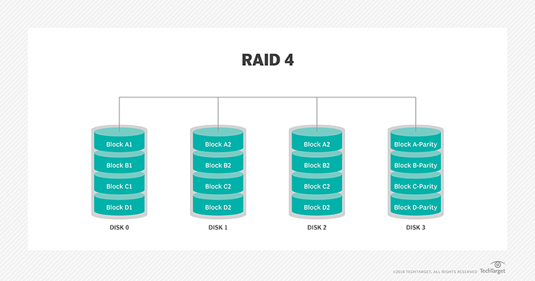
RAID 4: This level uses large stripes, which means you can read records from any single drive. This allows you to use overlapped I/O for read operations. Since all write operations have to update the parity drive, no I/O overlapping is possible. RAID 4 offers no advantage over RAID 5.
RAID 4 diagram
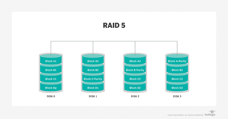
RAID 5This level is based on block-level striping with parity. The parity information is striped across each drive, allowing the array to function even if one drive were to fail. The array’s architecture allows read and write operations to span multiple drives. This results in performance that is usually better than that of a single drive, but not as high as that of a RAID 0 array. RAID 5 requires at least three disks, but it is often recommended to use at least five disks for performance reasons.
RAID 5 arrays are generally considered to be a poor choice for use on write-intensive systems because of the performance impact associated with writing parity information. When a disk does fail, it can take a long time to rebuild a RAID 5 array. Performance is usually degraded during the rebuild time and the array is vulnerable to an additional disk failure until the rebuild is complete.
RAID 5 diagram
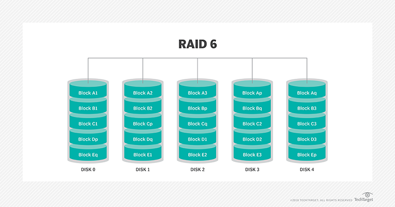
RAID 6: This technique is similar to RAID 5 but includes a second parity scheme that is distributed across the drives in the array. The use of additional parity allows the array to continue to function even if two disks fail simultaneously. However, this extra protection comes at a cost. RAID 6 arrays have a higher cost per gigabyte (GB) and often have slower write performance than RAID 5 arrays.
RAID 6 diagram

Nested RAID levels

Some RAID levels are referred to as nested RAID because they are based on a combination of RAID levels. Here are some examples of nested RAID levels.

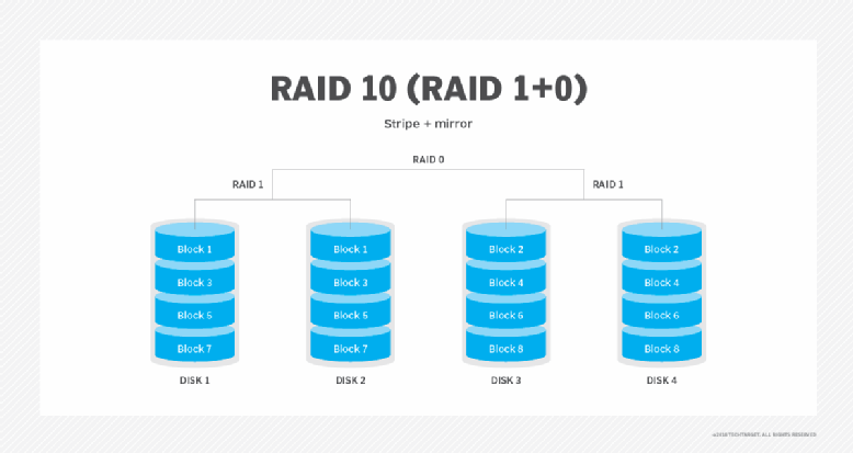
RAID 10 (RAID 1+0): Combining RAID 1 and RAID 0, this level is often referred to as RAID 10, which offers higher performance than RAID 1 but at a much higher cost. In RAID 1+0, the data is mirrored and the mirrors are striped.
RAID 10 diagram

8085 Programming


8085 Assembly Language Programs & Explanations1. Statement
: Store the data byte 32H into memory location 4000H.

Program 1:

MVI A, 32H : Store 32H in the accumulator

STA 4000H : Copy accumulator contents at address 4000H HLT : Terminate program execution


Program 2:

PROGRAM TO LOAD  A WITH 30H ,B WITH 44H ,H WITH 93H.

ANS:

ALOGRITHM:

STEP 1: LOAD  A WITH 30H
 STEP 2: LOAD B WITH 44H
STEP 3:LOAD H WITH 93H
STEP 4: STOP

MVI  A, 30H  ;  (LOAD  A WITH 30H)
MVI  B,44H ;   (LOAD B WITH 44H)
MVI H,93H ;(lOAD  H WITH 93H)
HLT   ;

Program 3:

LOAD B  AND C WITH DATA BYTES 65H AND 87H  .  ADD B WITH C, AND STORE RESULT IN B.

ANS:

ALGORITHM:

STEP 1: LOAD B REG. WITH 65H
STEP 2: LOAD C REG. WITH 87H
STEP 3: LOAD ACCUMULATOR  WITH B REG.
STEP 4:ADD  A REG WITH B REG.
STEP 5: STORE RESULT IN B REGISTER.
STEP 6: STOP.
PROGRAM :
   MVI  B,   65H   ; LOAD  B REG. WITH 65H
MVI    C,   87H ; LOAD C REG. WITH 87H
MOV  A,   B    ;  LOAD  A REG. WITH B REG.
ADD  C   ;    A REG <---A  REG.+ B REG.
MOV  B,  A   ; STORE RESULT IN B REG.
HLT   ;  STOP

Program 4:
ADD  THE CONTENTS OF TWO MEMORY LOCATIONS D000H AND D0001H. STORE RESULT IN MEMORY LOCATION D002H.

ALGORITHM :

STEP 1: LOAD FIRST   NUMBER FROM MEMORY LOCATION D000H.

STEP 2:LOAD  SECOND NUMBER FROM  MEMORY LOCATION D001H.

STEP 3:ADD FIRST  NUMBER  WITH SECOND NUMBERS.

STEP 4: STORE RESULT  TO MEMORY  LOCATION  D002H.

STEP 5: STOP.

PROGRAM :

LDA D000H  ; LOAD FIRST NUMBER FROM D000H IN A REG.
MOV  B, A   ; COPY  IT TO B REG.
LDA  D001H  ; LOAD SECOND NUMBER FROM D001H IN
ADD  B      ;  LOAD   A REG.<---A REG. + B REG.
STA  D002H; STORE RESULT  AT MEMORY LOCATION D002H
HLT     ;


write a program addition of two 16-bit  numbers:

Program - 5.a: Add two 16-bit numbers - Source Program 1

Sample problem:

(4000H) = 15H
(4001H) = 1CH
(4002H) = B7H
(4003H) = 5AH
Result = 1C15 + 5AB7H = 76CCH
(4004H) = CCH
(4005H) = 76H

Source Program 1:
LHLD 4000H                : Get first I6-bit number in HL
XCHG                        : Save first I6-bit number in DE
LHLD 4002H                : Get second I6-bit number in HL
MOV A, E                : Get lower byte of the first number
ADD L                        : Add lower byte of the second number
MOV L, A                : Store result in L register
MOV A, D                : Get higher byte of the first number
ADC H                        : Add higher byte of the second number with CARRY
MOV H, A                : Store result in H register
SHLD 4004H                : Store I6-bit result in memory locations 4004H and 4005H.
HLT                        : Terminate program execution


Thursday, 25 February 2016

Instruction Format

Instruction Format :

what is instruction ?

ans:instruction is a command  to the microprocessor to perform a given task on a specified data.
Each  instruction has two parts:
(a)one is task to be performed,called the operation code..(op-code)
(b)the second is the data to be operated on ,called the operand.

THE  8085 ,instruction set is classified  into the following groups according to length..:

(1) 1-byte instructions:
A one byte instruction includes the op-code and operand in the same  byte.
example  :

MOV   B,  A


(2)2-byte instructions:
in a two byte instruction ,the first byte specifies the operation code and the second byte specifies the operand..

example:

MVI  A , 40H

(3)3-byte instructions:
in a three byte instruction ,the first byte specifies ,the op-code and the following two bytes specify the 16-bit address or 16bit-data.

example:

LXI H , 9000H


Interrupts in 8085 Microprocessor

First of all i want to discuss that what is Interrupt???????

Interrupt is a mechanism by which an I/O or an instruction can suspend the normal execution of processor and get itself serviced. Generally, a particular task is assigned to that interrupt signal. In the microprocessor based system the interrupts are used for data transfer between the peripheral  devices and the microprocessor. The processor will check the interrupts always at the 2nd T-state of last machine cycle.

Interrupt Service Routine(ISR):-A small program or a routine that when executed services
 the corresponding interrupting source is called as an ISR.

Maskable/Non-Maskable Interrupt:-An interrupt that can be disabled by writing some instruction is known as Maskable Interrupt otherwise it is called Non-Maskable Interrupt.

There are two types of interrupts used in 8085 Microprocessor:

1.Hardware Interrupts
2.Software Interrupts

There are 6 pins available in 8085 for interrupt:

TRAP
RST 7.5
RST6.5
RST5.5
INTR
INTA

Execution of Interrupts:-
When there is an interrupt requests to the Microprocessor then after accepting the interrupts Microprocessor send the INTA (active low) signal to the peripheral. The vectored address of particular interrupt is stored in program counter. The processor executes an interrupt service routine (ISR) addressed in program counter.

8085 Instructions

8085 Instructions:


(1)Arithmetic Instruction

(2)Branching Instruction 

(3)Data Transfer Instruction

(4)Logic Instruction

Arithmetic Instruction


There are some of the important instructions in 8085 microprocessor.

1. ADD: - The content of operand are added to the content of the accumulator and the result is stored in Accumulator.

Eg- ADD B  (it adds the content of accumulator to the content of the register B)
     
      ADD M (if content is stored in memory location the it is added with the content stored in accumulator)


2. ADC: -

addition with carry

Eg:- ADC B  ,   ADC M


3. ADI: - Add immediate means add an immediate value withe the content of accumulator and it is stored in accumulator.

Eg: - ADI 30H


4. ACI: - Add immediate to accumulator with carry.

Eg: - ACI 40H

Memory Pointing Instruction :
5. LXI: Load register Pair immediate

Eg:- LXI H, 2030H (This instruction loads the memory address in HL register, here it works as memory pointer)


6. DAD: -  Add register pair to HL registerThe 16-bit contents of the specified register pair are 
added to the contents of the HL register and the sum is stored in the HL register. The contents of the source register pair are not altered. If the result is larger than 16 bits, the CY flag is set. No other flags are affected.
Subtraction Instruction :
7. SUB: -  substract the content of a register or a memory location form the content of accumulator and the result is stored in the accumulator.

Eg: - SUB B( it substracts the content of B register from the content of the accumulator.

         SUB M( it substracts the content of memory location pointed by HL pair from the content of

         
accumulator.


8. SBB: -  substract with borrow.


Eg: - SBB B
         SBB M


9.SUI: - Substract immediate from accumulator. this instruction subtract the immediate data from the content of accumulator and the result is store in accumulator.

Eg: - SUI 45H


10.SBI: - Substract immediate from the content of the accumulator and the result is stored in accumulator.

Increment and Decrement Instruction:
11. INR: - The contents of the designated register or memory) are incremented by 1 and the result is stored in the same place. If the operand is a memory location, its location is specified by the contents of the HL registers.

Eg: -INR B( the content of register B is incremented by 1.
       INR M( the content of memory location pointed by HL pair in incremented by 1)


12. INX: - Increment register pair by 1.

Eg: INX H (It means the location pointed by the HL pair is incremented by 1)


13.DCR: - The contents of the designated register or memory are M decremented by 1 and the 
result is stored in the same place. If the operand is a memory location, its location is specified by the contents of the HL registers.

Eg: - DCR B(content of register B is decremented by 1)
         DCR M(the content of memory location pointed by the HL pointer is decremented by 1.)

14. DCX: - decrement the register pair by 1.


Eg: DCX H( it decreases the memory location pointed by HL pair by 1.


15. DAA: - Decimal adjust accumulator.

The contents of the accumulator are changed from a binary value to two 4-bit binary coded decimal (BCD) digits. This is the only instruction that uses the auxiliary flag to perform the binary to BCD conversion, and the
conversion procedure is described below. S, Z, AC, P, CY flags are altered to reflect the results of the operation.
If the value of the low-order 4-bits in the accumulator is greater than 9 or if AC flag is set, the instruction adds 6 to the low-order four bits. If the value of the high-order 4-bits in the accumulator is greater than 9 or if the Carry flag is set, the instruction adds 6 to the high-order four bits.


Branching Instruction 

1. JMP: -  (unconditionally jump) The program sequence is transferred to the memory location specified by the16-bit address given in the operand.
Eg: - JMP 2034H ( jump to location 2034H) there is no condition to jump.
         JMP ABC (jump to abc level)


2. JC: - (conditional jump)  The program sequence is transferred to a particular level or a 16-bit address if C=1 (or carry is 1)
  

Eg: - JC ABC (jump to the level abc if C=1)


3. JNC:- (conditional jump) The program sequence is transferred to a particular level or a 16-bit address if C=0 (or carry is 0)

 Eg: JNC ABC (jump to the level abc if C=0)


4. JP: - (conditional jump) The program sequence is transferred to a particular level or a 16-bit address if S=0 (or sign is 0)

 Eg: - JP ABC (jump to the level abc if S=0)


 5. JM: - (conditional jump) The program sequence is transferred to a particular level or a 16-bit address if S=1 (or sign is 1)

 Eg: - JM ABC (jump to the level abc if S=1)


6. JZ: - (conditional jump) The program sequence is transferred to a particular level or a 16-bit address if Z=1 (or zero flag is 0)

 Eg: - JZ ABC (jump to the level abc if Z=1)


 7. JNZ: - (conditional jump) The program sequence is transferred to a particular level or a 16-bit address if Z=0 (or zero flag is 0)

 Eg: - JNZ ABC (jump to the level abc if Z=0)


8.JPE: -  (conditional jump) The program sequence is transferred to a particular level or a 16-bit address if P=1 (or parity flag is 1)

 Eg: - JPE ABC (jump to the level abc if P=1)


9. JPO: -  (conditional jump) The program sequence is transferred to a particular level or a 16-bit address if P=0 (or parity flag is 0)

 Eg: - JPO ABC (jump to the level abc if P=0)


1. CC: - (conditional call)  The program sequence is transferred to a particular level or a 16-bit address if C=1 (or carry is 1)
  
Eg: - CC ABC (jump to the level abc if C=1)
2. CNC: - (conditional call)  The program sequence is transferred to a particular level or a 16-bit address if C=0 (or carry is 0)
  
Eg: - CNC ABC (jump to the level abc if C=0)
3. CP: - (conditional call)  The program sequence is transferred to a particular level or a 16-bit 
address if S=0 (or sign is 0)
  
Eg: - CP ABC (jump to the level abc if S=0)
4. CM: - (conditional call)  The program sequence is transferred to a particular level or a 16-bit address if S=1 (or sign is 1)
  
Eg: - CM ABC (jump to the level abc if S=1)
5. CZ: - (conditional call)  The program sequence is transferred to a particular level or a 16-bit address if Z=1 (or zero flag is 1)
  
Eg: - CZ ABC (jump to the level abc if Z=1)
6. CNZ: - (conditional call)  The program sequence is transferred to a particular level or a 16-bit address if Z=0 (or zero flag is 0)
  
Eg: - CNZ ABC (jump to the level abc if Z=0)
7. CPE: - (conditional call)  The program sequence is transferred to a particular level or a 16-bit address if P=1 (or parity is 1)
  
Eg: - CPE ABC (jump to the level abc if P=1)
8. CPO: - (conditional call)  The program sequence is transferred to a particular level or a 16-bit address if P=0 (or parity is 0)
  
Eg: - CPO ABC (jump to the level abc if P=0)

Return Instruction :
The program sequence is transferred from the subroutine to the calling program based on the specified flag of the PSW as described below. The two bytes from the top of the stack are copied into the program counter, and program execution begins at the new address.
1. RC: - (conditional call)  The program sequence is transferred to a particular level or a 16-bit address if C=1 (or carry is 1)
  
Eg: - RC ABC (jump to the level abc if C=1)
2. RNC: - (conditional call)  The program sequence is transferred to a particular level or a 16-bit 
address if C=0 (or carry is 0)
  
Eg: - RNC ABC (jump to the level abc if C=0)
3. RP: - (conditional call)  The program sequence is transferred to a particular level or a 16-bit address if S=0 (or sign is 0)
  
Eg: - RP ABC (jump to the level abc if S=0)
4. RM: - (conditional call)  The program sequence is transferred to a particular level or a 16-bit address if S=1 (or sign is 1)
  
Eg: - RM ABC (jump to the level abc if S=1)
5. RZ: - (conditional call)  The program sequence is transferred to a particular level or a 16-bit address if Z=1 (or zero flag is 1)
  
Eg: - RZ ABC (jump to the level abc if Z=1)
6. RNZ: - (conditional call)  The program sequence is transferred to a particular level or a 16-bit address if Z=0 (or zero flag is 0)
  
Eg: - RNZ ABC (jump to the level abc if Z=0)
7. RPE: - (conditional call)  The program sequence is transferred to a particular level or a 16-bit address if P=1 (or parity is 1)
  
Eg: - RPE ABC (jump to the level abc if P=1)
8. RPO: - (conditional call)  The program sequence is transferred to a particular level or a 16-bit address if P=0 (or parity is 0)
  
Eg: - RPO ABC (jump to the level abc if P=0)
9.RET: - Return from  subroutine unconditionally

Program Counter :
1. PCHL: - Load program counter with HL contents. The contents of registers H and L are copied into the program counter. The contents of H are placed as the high-order byte and the contents of L as the low order byte.


2. RST: - The RST instruction is equivalent to a 1- byte call instruction to one of eight memory 
locations depending upon the number. The instructions are generally used in conjunction with interrupts and inserted using external hardware. However these can be used as software instructions in a program to transfer program execution to one of the eight locations.
The addresses are:

RST 0  0000H
RST1   0008H
RST 2  0010H
RST 3  0018H
RST 4  0020H
RST 5  0028H
RST 6  0030H
RST 7  0038H


Control Instruction
1.NOP(No operation): - No operation is performed. The instruction is fetched and decoded. However no operation is executed.
Eg: - NOP


2. HLT(Halt): - The CPU finishes executing the current instruction and halts any further 
execution. An interrupt or reset is necessary to exit from the halt state.
Eg: - HLT


3. DI(Disable Interrupt): - The interrupt enable flip-flop is reset and all the interrupts except the TRAP are disabled. No flags are affected.
Eg: - DI


4. EI(Enable Interrupt): - The interrupt enable flip-flop is set and all interrupts are enabled. No flags are affected. After a system reset or the acknowledgement of an interrupt, the interrupt enable flipflop is reset, thus disabling the interrupts. This instruction is necessary to reenable the interrupts (except TRAP).
Eg: - EI


5. RIM(Read interrupt mas): - This is a multipurpose instruction used to read the status of interrupts 7.5, 6.5, 5.5 and read serial data input bit. The instruction loads eight bits in the accumulator with the following interpretations.
Eg: - RIM


6.SIM(Set interrupt mask)


Data Transfer Instruction


1.MOV: - This instruction is used to copy the data from one place to another.

Eg: - MOV Rd, Rs (This instruction copies the content of Rs to Rd)
         MOV M,Rs (This instruction copies the content of register Rs to memory location pointed by HL Register)
         MOV Rd, M (This instruction copies the content of memory location pointed by the HL 
register to the register Rd.)


2.MVI: -
 move immediate date to a register or memory location.


Eg: - MVI Rd, #30H (30h is stored in register Rd)

          MVI M, #30H(30h is stored in memory location pointed by HL Reg)


3.LDA: - Load accumulator. (this instruction copies the data from a given 16 bit address to the accumulator)

Eg: - LDA 3000H (content of memory location 3000h is coppied in accumulator)


4.LDAX(Load accumulator indirect): - The contents of the designated register pair point to a memory location. This instruction copies the contents of that memory location into the accumulator. The contents of either the register pair or the memory location are not altered.

Eg: - LDAX B


5.LXI(Load register pair immediate): - The instruction loads 16-bit data in the register pair designated in the
operand.
Eg: - LXI H, 2034H (2034H is stored in HL pair so that it act as memory pointer)
          
          LXI H, XYZ      (address of level XYZ is copied in HL pair)


6.LHLD(Load H and L register direct): - this instruction loads the contents of the 16- bit memory location into the HL register pair.

Eg: - LHLD 3000H (the content of location 3000h is copied into the HL reg pair)


7.STA: - the content of accumulator are copied into the memory location.

Eg: - STA 3000H (the content of accumulator is stored into the memory location 3000h)


8.STAX(Store accumulator indirect): - The contents of the accumulator are copied into the memory location specified by the contents of the operand (register pair). The contents of the accumulator are not altered.

Eg: - STAX B (the content of accumulator is stored into the memory location specified by the BC register pair.)


9.SHLD(store H and L register direct): - The contents of register L are stored into the memory location specified by the 16-bit address in the operand and the contents of H register are stored into the next memory location by incrementing the operand. The contents of registers HL are not altered. This is a 3-byte instruction, the second byte specifies the low-order address and the third byte specifies the high-order address.


Eg: - SHLD 3000H


10. XCHG: - Exchange H and L with D and E. The contents of register H are exchanged with the contents of register D, and the contents of register L are exchanged with the contents of register E.

Eg: - XCHG


11. SPHL: - This instruction copies H and L register to the stack pointer. The instruction loads
the contents of the H and L registers into the stack pointer register, the contents of the H register provide the highorder address and the contents of the L register provide the low-order address. The contents of the H and L registers are not altered.

Eg: - SPHL


12.  XTHL: - This instruction exchanges H and L with top of stack. The contents of the L register are exchanged with the stack location pointed out by the contents of the stack pointer register. The contents of the H register are exchanged with the next stack location (SP+1); however, the contents of the stack pointer register are not altered.

Eg: - XTHL


13.  PUSH: - This instruction pushes the register pair onto stack. The contents of the register pair designated in the operand are copied onto the stack in the following sequence. The stack pointer register is decremented and the contents of the highorder register (B, D, H, A) are copied into that location. The stack pointer register is decremented again and the contents of the low-order register (C, E, L, flags) are copied to that location.
 
Eg: - PUSH B 
          PUSH A


14. POP: - This instruction pop off stack to register pair. The contents of the memory location pointed out by the stack pointer register are copied to the low-order register (C, E, L, status flags) of the operand. The stack pointer is incremented by 1 and the contents of that memory location are copied to the high-order register (B, D, H, A) of the operand. The stack pointer register is again incremented by 1.
 
Eg: - POP H 
          POP A


15. OUT: - Output data from accumulator to a port with 8-bit addresses. The contents of the accumulator are copied into the I/O port specified by the operand.
Eg: OUT F8H


16.IN: - Input data to accumulator from a port with 8-bit address. The contents of the input port designated in the operand are read and loaded into the accumulator.
Eg: - IN 8CH


Logic Instruction


1. CMP: - (compare register or memory with accumulator) The contents of the operand  register or memory are M compared with the contents of the accumulator. Both contents are preserved . The result of the comparison is shown by setting the flags of the PSW as follows:

if (A) < reg/mem: carry flag is set.
if (A) = reg/mem:
zero flag is set.
if (A) > reg/mem: carry and zero flags are reset.

Eg: - CMP B
          CMP M


 2. CPI: - (compare immediate with accumulator) The second byte (8-bit data) is compared with the contents of the accumulator. The values being compared remain unchanged. The result of the comparison is shown by setting the flags of the PSW as follows:

if (A) < data: carry flag is set
if (A) = data: zero flag is set
if (A) > data: carry and zero flags are reset 

Eg: - CPI 89H


3. ANA: - logical AND operation is performed with the specified register or memory with accumulator.
Eg: - ANA B
          ANA M


4. ANI: - (AND operation with immediate data) AND operation is performed between accumulator and specified immediate data.

Eg: - ANI 30H


5.XRA: - The content of accumulator are exclusive OR with specified register or memory location.

Eg: - XRA B
          XRA M


6. XRI: - The content of accumulator are exclusive OR with the immediate data.

Eg: - XRI 30H


7. ORA: - Logical OR operation is performed between accumulator and specified register and memory location.

Eg: - ORA B
          ORA M


8. ORI: - Logical OR operation is performed between accumulator and immediate data.


Eg: -
 ORI 30H


Instruction 2 :
1. RLC: - Each binary bit of the accumulator is rotated left by one position. Bit D7 is placed in the position of D0 as well as in the Carry flag. CY is modified according to bit D7. Any other bit is not affected.


Eg: - RLC


2. RRC: -  Each binary bit of the accumulator is rotated right by one position. Bit D0 is placed in the position of D7 as well as in the Carry flag. CY is modified according to bit D0. Any other bit is not affected.

Eg: - RRC


3. RAL: - Each binary bit of the accumulator is rotated left by one position through the Carry flag. Bit D7 is placed in the Carry flag, and the Carry flag is placed in the least significant position D0. CY is modified according to bit D7.


Eg: - RAL


4. RAR: - Each binary bit of the accumulator is rotated right by one position through the Carry flag. Bit D0 is placed in the Carry flag, and the Carry flag is placed in the most significant position D7. CY is modified according to bit D0.

Eg: - RAR


5. CMA: - The content of accumulator is complemented.
Eg: - CMA


6. CMC: - The carry flag is complemented.
Eg: - CMC


7. STC: - This instruction sets the carry flag.

Eg: - STC


Disqus Shortname

Ads Top

About Me

My photo
Technical Trainer for Full Stack Web Development & Digital Marketing Course

Comments system

Popular Posts

Navigation-Menus (Do Not Edit Here!)

Animation - Scroll IMG (yes/no)

Fixed Menu (yes/no)

Related Posts No. (ex: 9)

PageNavi Results No. (ex: 7)

Facebook

Advertising

Popular